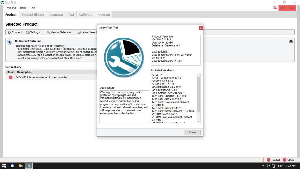
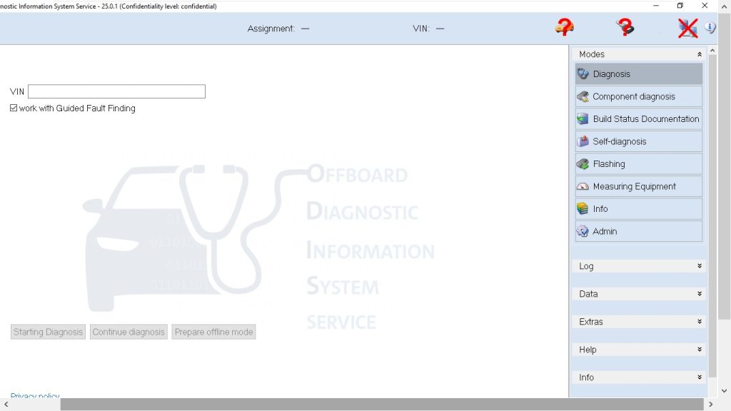
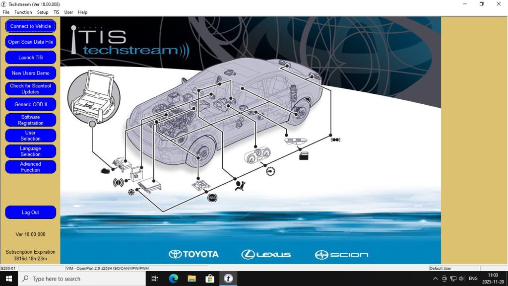
An electrical fault on a wheel loader or dozer that takes four hours to diagnose with a generic wiring book takes twenty minutes with the official CASE CE electrical schematic. The difference is connector location maps, wire color codes keyed to specific harness routing, and pin-level circuit diagrams that show exactly which ECU input is expected to be at what voltage under what operating condition.
What Makes a CASE CE Electrical Schematic Different
The CASE CE Electrical Schematics are machine-specific, Tier-level-specific, and serial-number-specific documents. This is important because Tier 4A and Tier 4B Final machines have additional wiring for:
- DEF (Diesel Exhaust Fluid) pump and quality sensor circuits
- DPF differential pressure sensor and temperature sensor
- SCR catalyst temperature monitoring
- Aftertreatment system warning lamp and forced regeneration interlock
Using a Tier 3 schematic on a Tier 4A machine for electrical diagnosis will not show these circuits, leading to misdiagnosis. The CE Electrical Schematics collection includes Tier 2, Tier 4A (Interim), and Tier 4B (Final) versions as separate PDFs.
Machine Coverage in the 64-PDF Collection
Wheel Loaders
- 521F, 621F, 721F, 821F, 921F — Tier 4B (Final) electrical schematics
- 1021F, 1121F — Tier 2 and Tier 4B variants
- 1221F — Tier 4 schematic
Crawler Dozers
- 850M — Tier 4A (Interim), RAC 47907889 (replaces 47621946)
- 1150M — Tier 2 (pin break NGC105100 and after) + Tier 4B Final
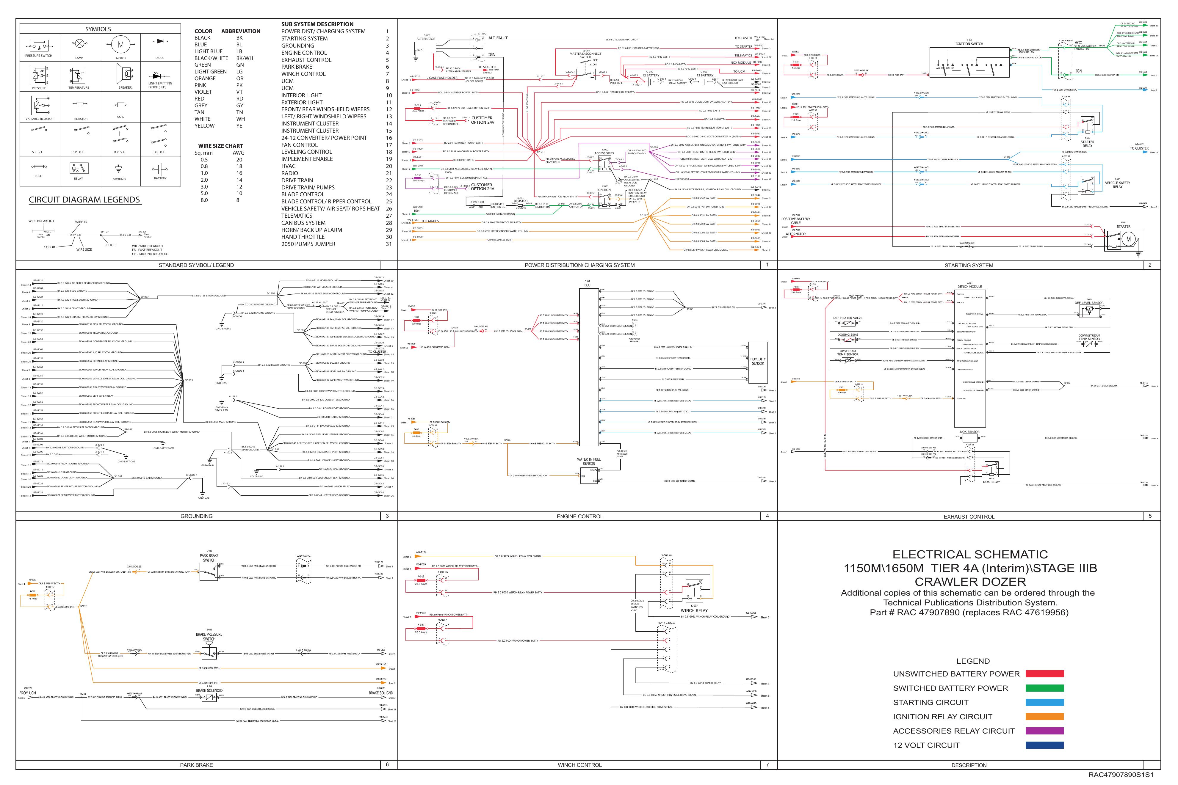
- 1150M/1650M — Tier 4A Interim Stage IIIB combined schematic
- 1650M — Tier 2 (pin break NGC107000 and after) + Tier 4B Final
- 2050M — Tier 4A Interim + Tier 4B Final (pin break NGC109000 and above)
Excavators
- CX290C — Full electrical schematic
Skid Steer Loaders
- SR130, SR150, SR175, SV185, SR200, SR220, SR250, SV250, SV300 — Alpha Series mechanical schematic
Connector Diagrams
- 333F, 335F, 335M, 336M — Pin-level connector diagrams for harness diagnosis
How to Use These Schematics for Diagnosis
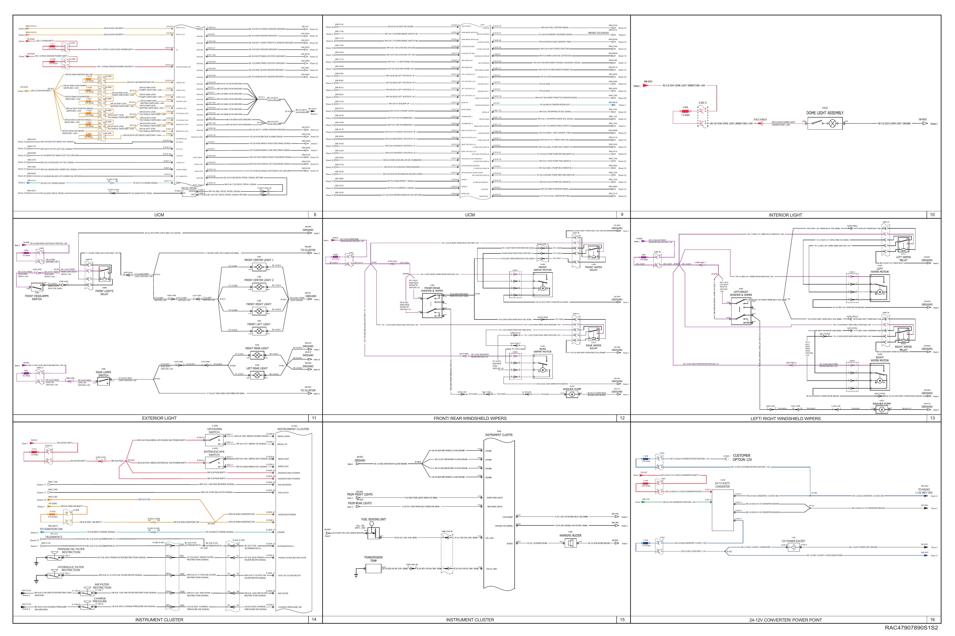
Each schematic PDF is formatted at full A3 resolution — the wire gauges, connector designations, and component identifiers are legible when printed at scale or zoomed on a tablet. The diagnostic workflow with these documents:
- Identify the fault circuit — Fault code DTC cross-references the relevant schematic sheet in the manual index.
- Locate the connector — Each connector has an identifier (e.g., C003, P017) that appears in both the circuit diagram and the connector location diagram showing its physical position on the machine.
- Test at the ECU pin — The schematic shows the ECU connector and the pin number for each signal, allowing a back-probe test to confirm whether the fault is in the sensor, harness, or ECU.
- Verify power and ground paths — The power distribution sheet shows every fuse, relay, and ground point with wire gauge and color, so voltage-drop testing takes minutes instead of hours.
Pin-Break Specific Versions — Why This Matters
CASE issued multiple revisions of some schematics tied to specific serial number breakpoints (called PIN breaks). For example, the 1150M Tier 2 schematic applies only to machines with PIN NGC105100 and after — earlier machines have a different wiring revision. The collection includes both versions where applicable, with the PIN break range noted in the filename.
Download the CASE CNH Electrical Schematics Collection
Frequently Asked Questions
Are these the same documents available in CNH Service Information (SI)?
Yes. These are the OEM PDFs — the same files that dealerships download from CNH SI. The advantage of this collection is permanent offline access without an annual SI subscription.
Do the schematics include hydraulic circuit diagrams?
Some machines have a combined electrical/hydraulic schematic document. Most of the PDFs in this collection are dedicated electrical schematics. Hydraulic schematics are contained within the machine-specific service manuals (Backhoe Loader, Excavator, Wheel Loader collections).
What format are the connector diagrams in?
The 333F, 335F, and 335M connector diagrams are separate PDFs showing pin layouts and wire routing for the main chassis connectors used across multiple machine types in the F and M series.