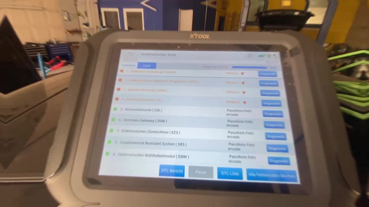
The tutorial uses XTOOL (BENZ V24.30) together with Mercedes XENTRY/DAS, a Hantek 6022BE oscilloscope and an OBD Break‑Out Box to diagnose a complete CAN‑bus failure on a W204 C‑Class. By combining automatic scans, voltage checks and real‑time signal analysis, technicians can pinpoint the exact module or wiring fault that prevents cranking, horn operation and infotainment activation.
What You Will Learn
- How to run an automatic system scan with XTOOL (BENZ V24.30) and capture all DTCs.
- How to verify power supply at Kl. 30 and Kl. 15 terminals for critical control units.
- How to measure CAN‑bus line resistance and interpret the results.
- How to use a Hantek 6022BE oscilloscope to view and diagnose distorted CAN signals.
- How to isolate a faulty CAN segment by disconnecting modules and using the OBD Break‑Out Box.
- How to clear fault codes and confirm successful communication restoration.
- How to document the repair process for future reference.
Step-by-Step Walkthrough
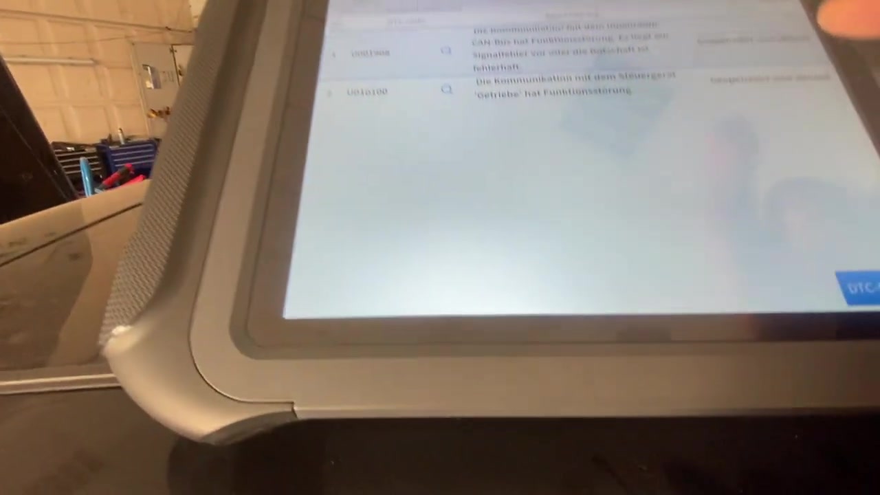
Start by connecting the XTOOL (BENZ V24.30) cable to the OBD‑II port of the W204 and launch Mercedes XENTRY/DAS. Select Automatic System Scan and let the software poll every ECU. The scan immediately returns multiple errors, including U001908 (CAN bus interior communication fault) and U010100 (TCU communication fault). The diagnostic screen shows a red “No connection between diagnostic gateway and control unit” warning, confirming a network‑wide issue.
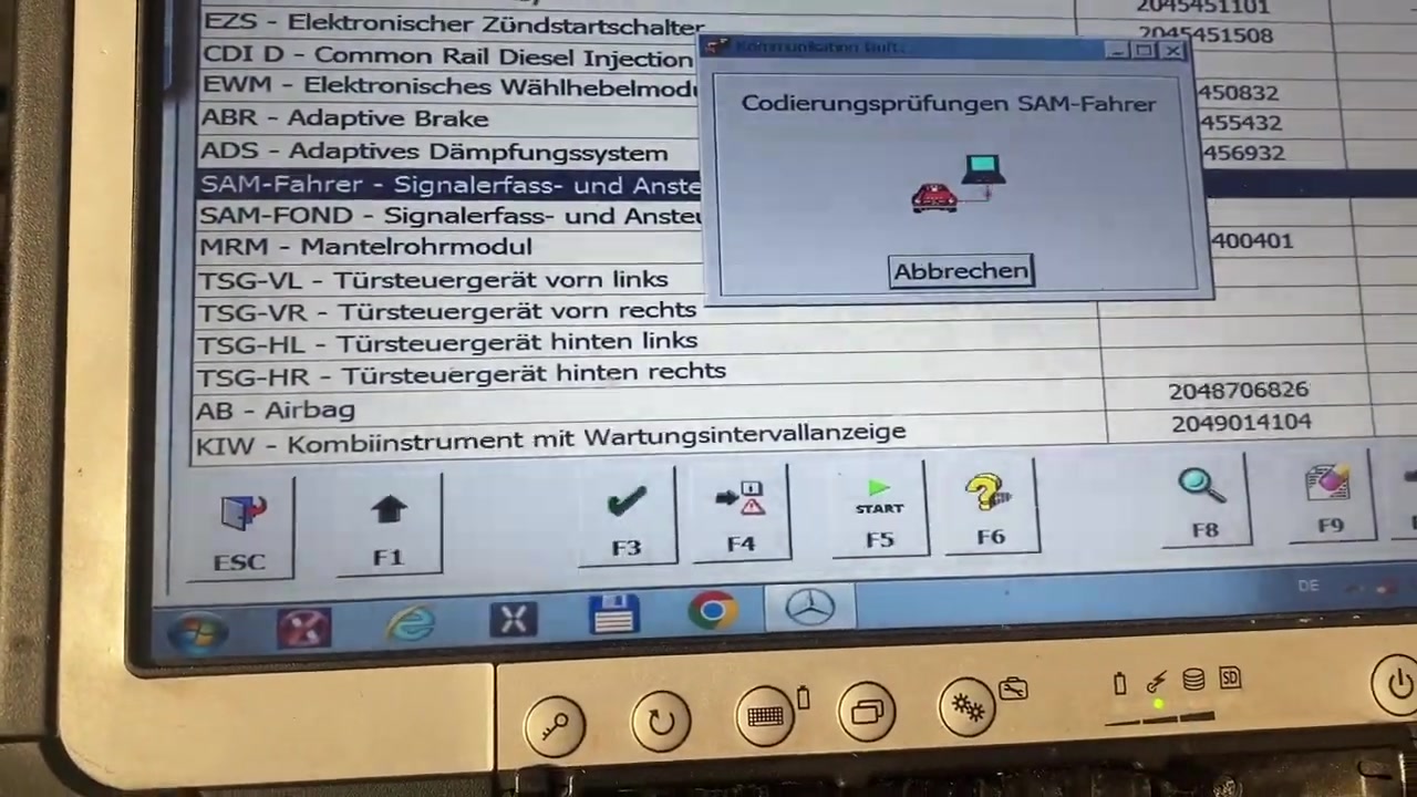
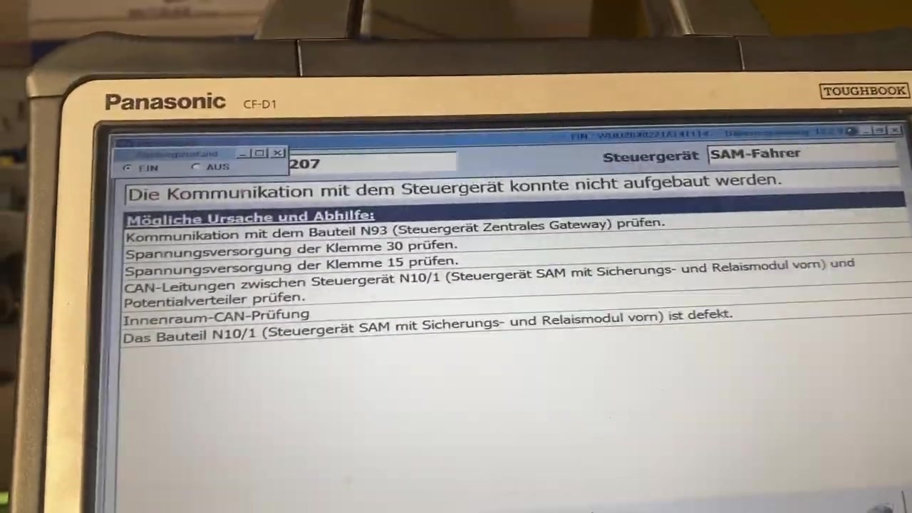
Next, open the Topology View to visualize the CAN‑bus layout. The graphical map highlights the SAM (Signal Acquisition Module) front module N10/1 as the only node with a broken link icon. Click the node to read live voltage data; both Kl. 30 (battery) and Kl. 15 (ignition) are present, but the SAM voltage drops to 0 V when the ignition is on, indicating a power loss inside the module.
Proceed to the Voltage Supply Check screen. Using a multimeter, probe the SAM’s power pins. Record the readings: 12.6 V at Kl. 30, 0 V at Kl. 15. This confirms that the fuse/relay circuit feeding the SAM is defective. Replace the N10/1 unit and re‑run the automatic scan. The same errors persist, suggesting a deeper wiring problem.
Now switch to the CAN Line Resistance function. Disconnect the main CAN‑H and CAN‑L cables at the diagnostic connector, then measure resistance with the XTOOL built‑in tester. The reading shows 60.3 Ω, far above the acceptable <5 Ω limit. This high resistance points to a short or corrosion somewhere in the bus.
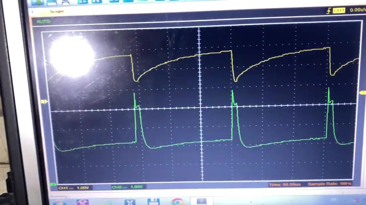
To visualise the fault, connect the Hantek 6022BE oscilloscope to the CAN‑H line via the OBD Break‑Out Box. Set the scope to 500 kHz bandwidth, 2 µs/div horizontal scale, and trigger on the falling edge of the CAN‑H waveform. The display shows a severely distorted signal with missing recessive periods and irregular dominant pulses.
Such distortion prevents any ECU from recognizing valid frames.
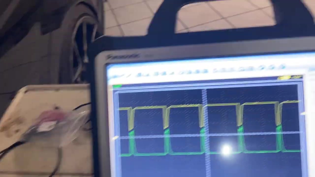
Isolate the network by disconnecting the rear‑door modules, the infotainment unit and the horn relay one at a time, checking the oscilloscope after each removal. After unplugging the rear‑door SAM, the CAN signal returns to a clean square‑wave pattern. This indicates that the rear‑door SAM is introducing the fault, likely due to water ingress.
Open the rear‑door SAM housing and inspect the PCB. Visible corrosion and a burnt resistor are found on the CAN transceiver. Replace the damaged SAM, re‑install, and re‑measure the bus resistance – it now reads 3.8 Ω, well within spec. Re‑connect the OBD Break‑Out Box and run a quick Communication Check for each ECU. All modules respond correctly.
Return to XENTRY/DAS, clear all stored DTCs, and perform a final System Scan. The scan reports no errors, and the vehicle now cranks, the horn sounds, and the infotainment lights up. Verify by starting the engine and listening for normal operation. Document the entire process with screenshots saved from XTOOL and the oscilloscope for the service record.
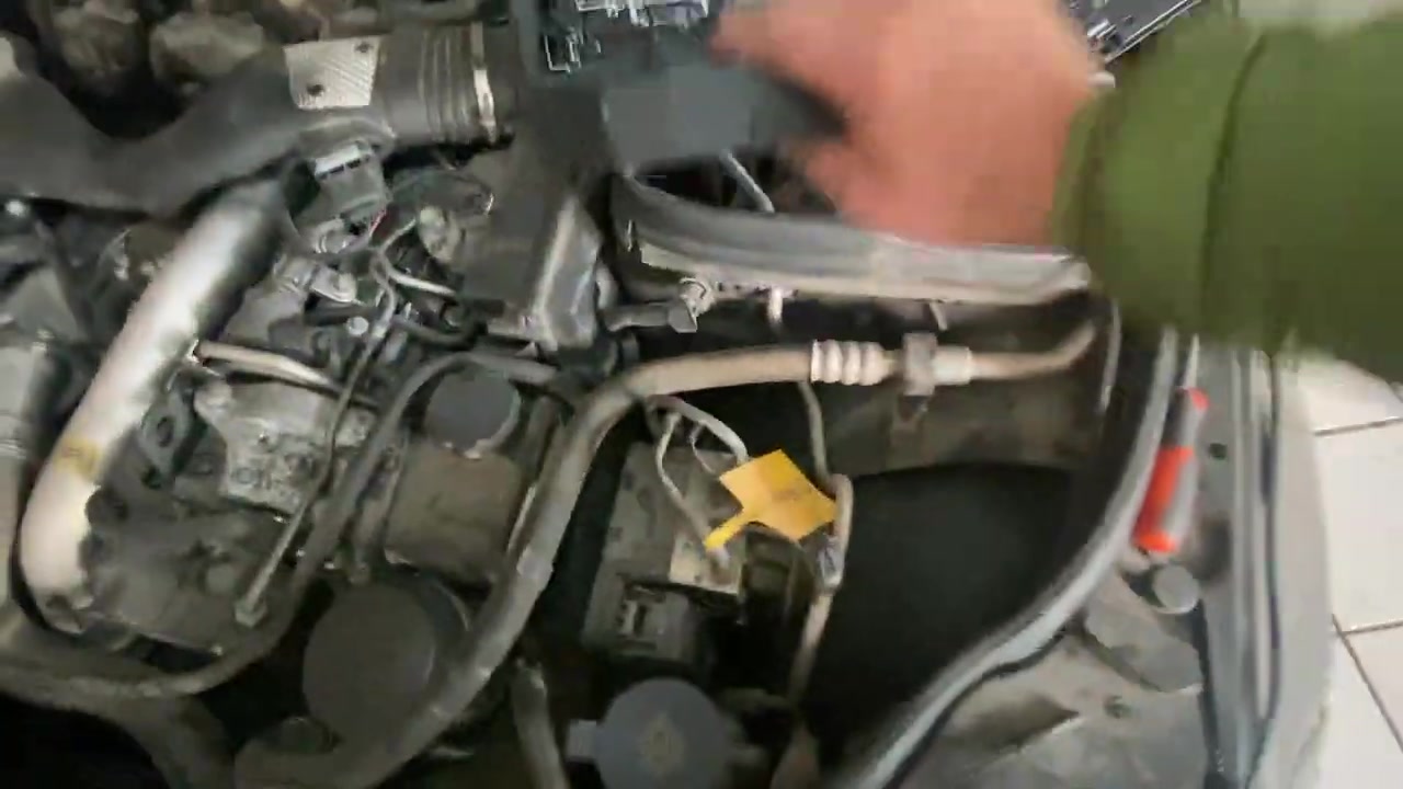
Key Features of XTOOL (BENZ V24.30), Mercedes XENTRY/DAS, Hantek oscilloscope (6022BE), OBD Break Out Box
- Automatic system scan that queries every ECU and compiles a comprehensive DTC list.
- Topology view that maps the entire CAN‑bus architecture and highlights faulty nodes.
- Integrated voltage supply test for Kl. 30 and Kl. 15 on any selected module.
- CAN‑line resistance measurement tool with built‑in tolerance alerts.
- Real‑time oscilloscope interface via the OBD Break‑Out Box for signal integrity analysis.
- One‑click DTC clearing and verification of successful communication restoration.
Compatible Vehicles and ECUs
This procedure applies to all Mercedes‑Benz models that share the W204 platform, including the C‑Class (W204), CLK (C209), and early E‑Class (W212) variants that use the same CAN‑bus topology. The diagnostic steps cover the following ECUs: Engine Control Module (ECM), Transmission Control Unit (TCU), Central Gateway (G‑Gateway), Signal Acquisition Module (SAM), Body Control Module (BCM), Horn Relay, and Infotainment Control Unit.
Pro Tips
- Always start with the automatic scan; it saves time by pointing directly to the malfunctioning node.
- Check both battery (Kl. 30) and ignition (Kl. 15) voltages before assuming a communication fault.
- Measure CAN resistance with the bus disconnected; a reading above 5 Ω indicates a wiring defect.
- Use the oscilloscope to differentiate between a shorted line (flat signal) and a corrupted transceiver (distorted waveform).
- When isolating a fault, disconnect modules in logical groups to quickly narrow down the problematic segment.
Following this structured approach with XTOOL (BENZ V24.30) and supporting hardware enables technicians to resolve complex CAN‑bus failures efficiently, restoring full vehicle functionality without guesswork.
Frequently Asked Questions
My Mercedes W204 won’t start and has multiple electrical faults. What could be the cause?
The video demonstrates that a faulty CAN bus module, specifically the front SAM unit (N10/1), can cause widespread communication issues leading to no-start conditions and various electrical malfunctions like non-functional horn or radio.
How do I diagnose a CAN bus communication fault in a Mercedes?
The video shows using a diagnostic scanner (XTOOL, XENTRY/DAS) to read DTCs, checking for “no communication” errors. It also involves measuring CAN line resistance (should be low, e.g., < 5 Ohm) and using an oscilloscope to analyze the CAN bus signal waveform for distortions.
What is the normal resistance for a CAN bus line?
The video indicates that the resistance between CAN High and CAN Low lines should be less than 5 Ohms when measured correctly. A higher reading (e.g., 60.3 Ohm) suggests a fault.
Looking for professional diagnostic software for trucks and heavy equipment? Visit firstdiag.com for instant digital downloads.