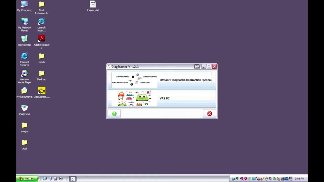
The Offboard Diagnostic Information System Service - 1.0.8 (ODIS) is a powerful VAG‑group diagnostic platform that runs on a laptop or tablet instead of a traditional VAS 5054A. This tutorial walks technicians through a complete guided‑fault‑finding session on a 2009 Audi Q5 (USA/CDN), demonstrating how to launch ODIS, identify the vehicle, read and erase DTCs, run user‑generated test plans, and access repair documents—all while using the Guided Functions that streamline complex procedures.
What You Will Learn
- How to start ODIS Service and configure the initial warning screens.
- Methods for automatic and manual vehicle identification.
- How to navigate the control‑module list, interpret DTC colors, and view measured values.
- How to use the networking diagram (topology view) to understand module communication.
- Steps to erase all DTCs safely and when to avoid doing so.
- How to launch, run, and save user‑generated test plans.
- How to retrieve repair documents, send support inquiries, and export diagnostic sessions.
Step-by-Step Walkthrough
The walkthrough follows the exact sequence shown in the video, integrating screenshot placeholders for easy reference.
1. Launch ODIS Service
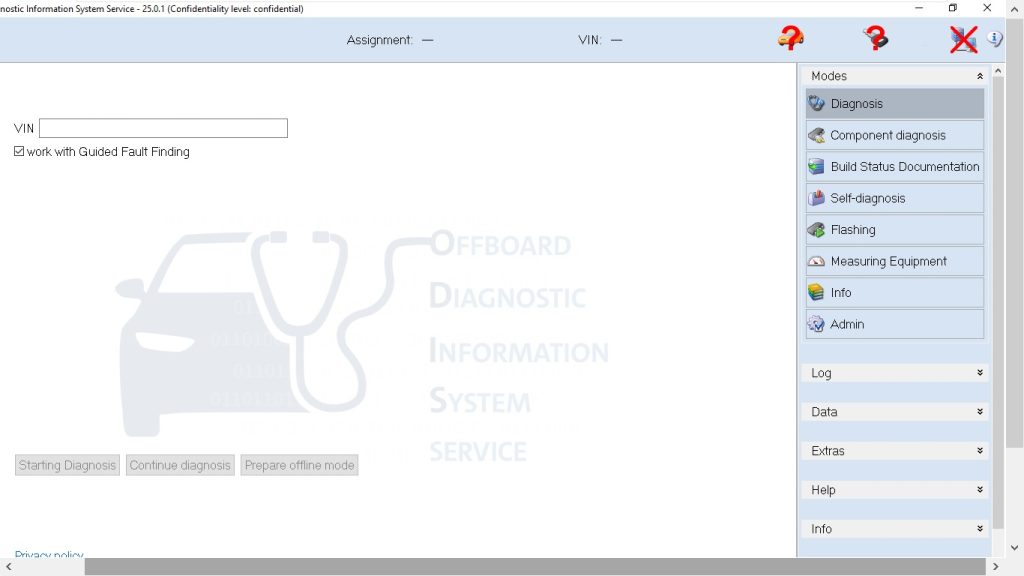
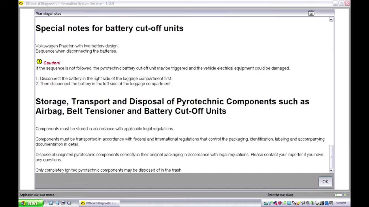
From the tool desktop double‑click the Diag Starter icon and select Offboard Diagnostic Information System Service. The release‑notes window appears, listing recent changes and a hyperlink to detailed notes. Scroll to the bottom, check the box to acknowledge the warnings, and click OK to proceed to the main screen.
2. Main Screen Overview
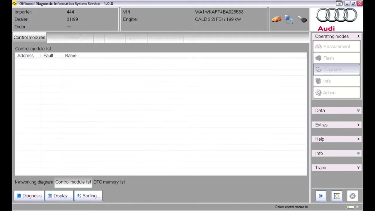
The ODIS main window is divided into several sections. The top information bar displays the importer, dealer order number, VIN, and engine code. Directly below, three status icons indicate vehicle detection, communication health, and whether Guided Fault Finding (GFF) is active. Ensure the “Work with Guided Fault Finding” checkbox is ticked; otherwise many advanced functions remain hidden.
3. Vehicle Identification
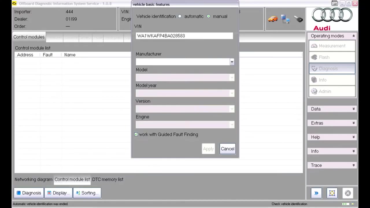
If the vehicle is detected automatically, ODIS populates the VIN, model, and engine fields. For manual entry, click Vehicle Identification, choose the correct market (USA/CDN), and confirm the pre‑filled data. Double‑check the model year and engine variant because a mismatched ECU can lead to false DTCs.
4. Viewing Control Modules and DTCs
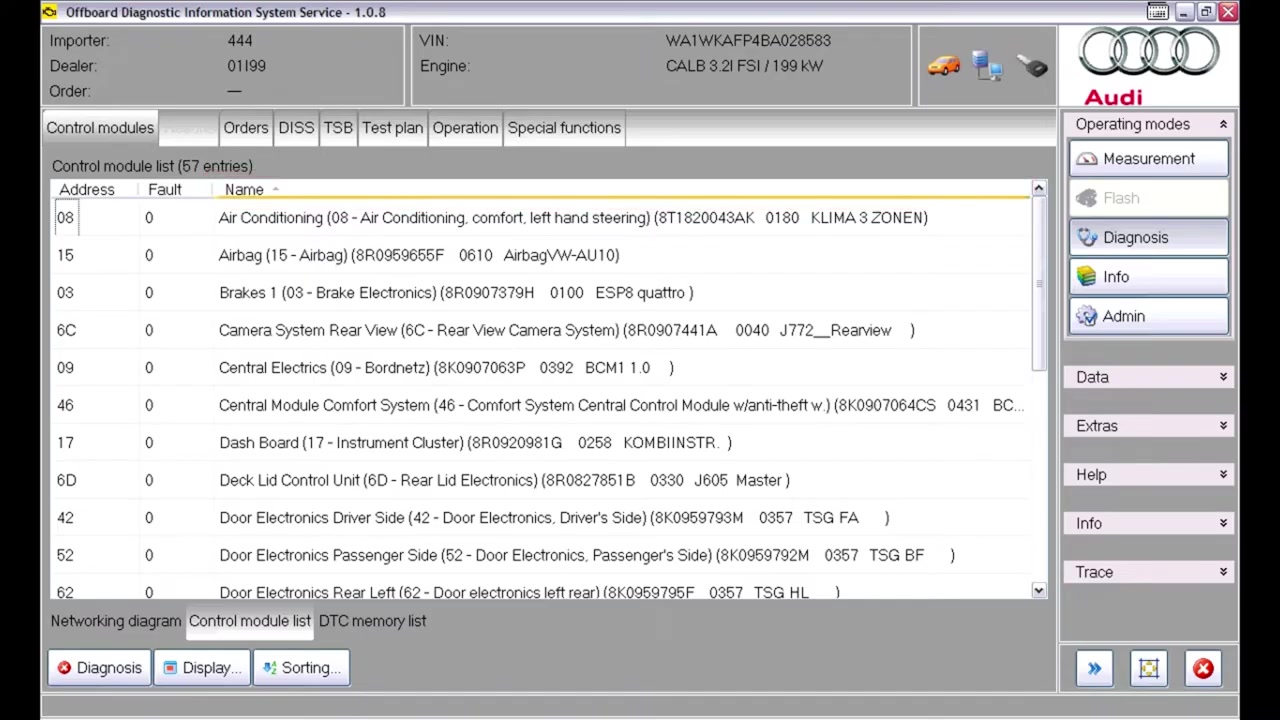
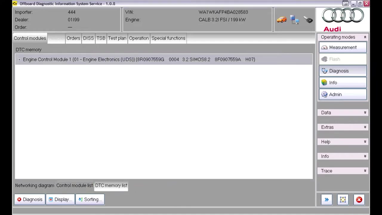
Select Control Modules from the left navigation pane. Modules that have stored DTCs appear in red; those that are offline or not installed are grayed out. Click any module to expand its fault list, then press Show DTCs to see code details, description, and occurrence count. Use the Measured Values tab under Guided Functions for live sensor data instead of the OBD raw view.
5. Networking Diagram (Topology View)
Open the Topology button to display a graphical map of the vehicle’s CAN/LIN bus architecture. Hover over each node to see its communication status. This view is essential when a module is gray because it often indicates a broken wiring harness or missing power supply.
6. Erasing DTCs
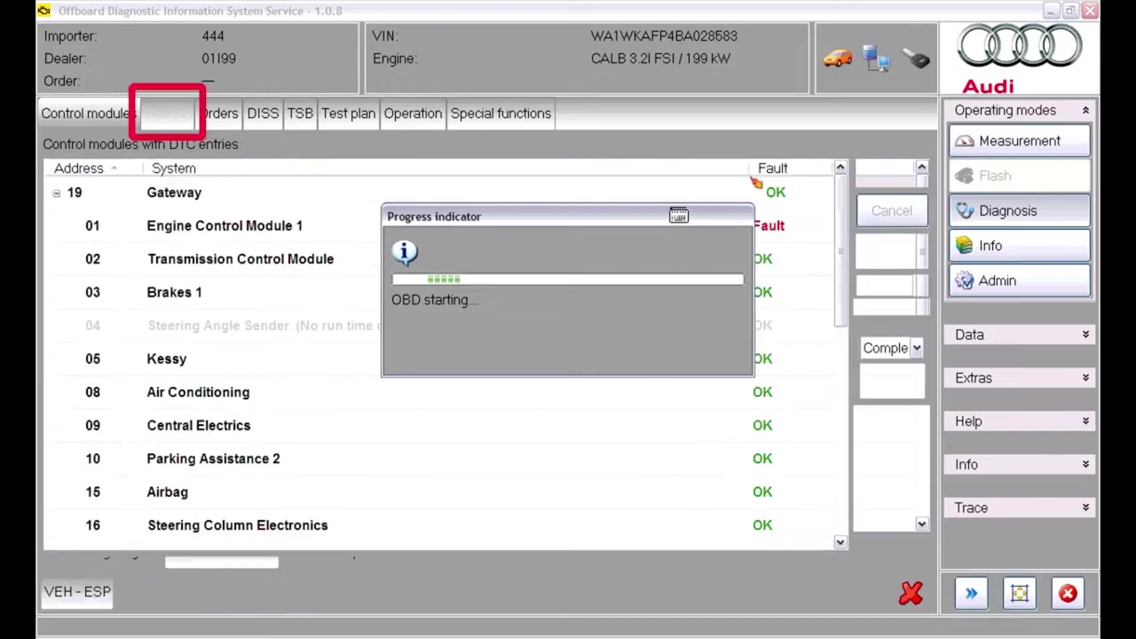
When all faults have been addressed, navigate to OBD Functions → Complete DTC Memory. A translation bug may label this option incorrectly; the underlying function remains the same. Confirm the erase operation, but remember the safety note: do not clear DTCs if an airbag fault is present and the airbag system has not been repaired.
7. Running a User‑Generated Test Plan
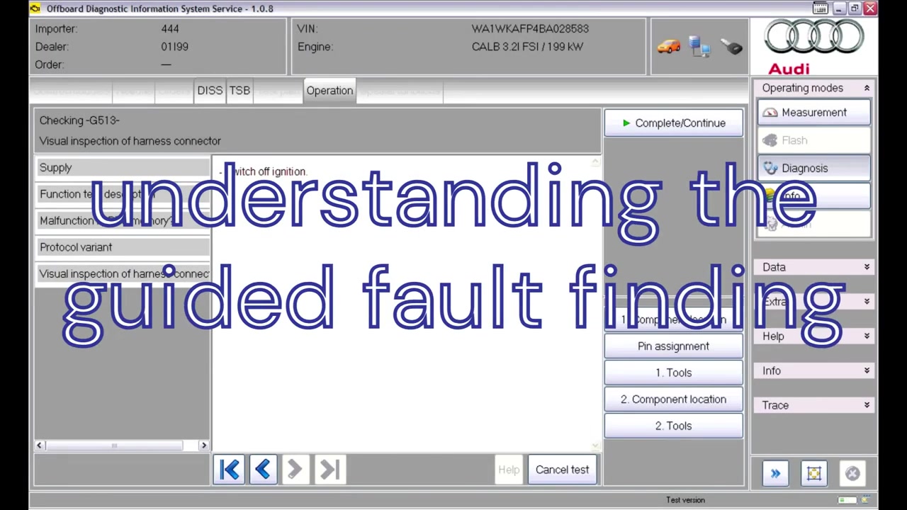
From the main menu choose Test Plans → Load and browse to the custom plan file. Once loaded, the steps appear in the right‑hand pane. Click Start to execute each step; ODIS will automatically advance to the next step only after the previous one is completed successfully. Test plans cannot be removed once loaded, so close the session if you need a clean slate.
8. Accessing Repair Documents and Support
Select Documents to open the repair‑information portal. Even documents marked “not translated” may contain useful diagrams; attempt to open them before dismissing. To contact technical support, click Send Inquiry and attach the saved diagnostic session file. The session can be saved at any point via File → Save Session and later reopened on any tester running the same ODIS version.
Key Features of Offboard Diagnostic Information System Service – 1.0.8
- Guided Fault Finding (GFF) that automatically creates step‑by‑step test plans based on detected DTCs.
- Automatic vehicle identification with fallback to manual VIN entry.
- Real‑time measured values displayed in an intuitive grid, bypassing raw OBD data.
- Network topology view that visualizes CAN/LIN bus health and module connections.
- Full OBD‑II functions, including complete DTC memory erase, transport mode activation, and component list retrieval.
- Ability to import and run custom test plans created by OEM engineers or third‑party specialists.
- Session management that allows saving, loading, and transferring diagnostics across multiple testers.
Compatible Vehicles and ECUs
The demonstration uses a 2009 Audi Q5 (USA/CDN) but ODIS 1.0.8 supports the entire VW‑Audi‑Seat‑Škoda family for model years 2005‑2022. Key ECUs covered include:
- Engine Control Module (ECM)
- Transmission Control Module (TCM)
- ABS/ESC Control Unit
- Airbag Control Module (ACM)
- Body Control Module (BCM)
- Instrument Cluster (IC)
- Central Convenience Module (CCM)
- Telematics Control Unit (TCU)
Pro Tips
- Read every warning and note screen after launching ODIS; the OK button stays grey until you scroll to the bottom.
- Always keep “Work with Guided Fault Finding” enabled to unlock the full suite of GFF tools.
- When manually entering vehicle data, verify the pre‑filled market, model year, and engine code against the VIN plate.
- Select “Yes” for the “specified/actual comparison” prompt to ensure the tester uses the exact ECU software version installed in the vehicle.
- Red‑highlighted modules contain active DTCs; gray modules indicate communication loss or missing hardware.
- Consult the latest repair information for updated topology diagrams before troubleshooting wiring issues.
- Never erase all DTCs if an airbag fault is present; clearing the memory can mask a safety‑critical condition.
- Use the “Measured values” option under Guided Functions for a cleaner, more readable sensor readout than the raw OBD view.
- Saved diagnostic sessions are portable across any tester with the same ODIS version—ideal for multi‑shop collaborations.
By mastering the workflow presented in this guide, technicians can reduce diagnostic time, avoid common pitfalls, and deliver precise repairs on Audi, VW, Seat, and Škoda vehicles using Offboard Diagnostic Information System Service - 1.0.8.
Frequently Asked Questions
How do I launch ODIS Service?
Double-click the DiagStarter icon on the desktop and select ‘Offboard Diagnostic Information System’.
What if ODIS doesn’t detect the vehicle or ignition?
A red X or question mark will appear on the respective icons, indicating a connection issue.
Can ODIS operate without an internet connection?
Yes, but functions like software version management, component protection unlocking, or diagnostic log uploading will not work.
How do I start Guided Fault Finding?
Ensure the data link connector is connected and the key is recognized, then select ‘Start diagnosis’ from the main screen.
How do I view DTCs?
Go to the ‘Control modules’ tab, then select the ‘DTC memory list’ lower tab. Expand the plus symbols to see details.
Ready to use Offboard Diagnostic Information System Service – 1.0.8 in your workshop? Download it directly from firstdiag.com — instant delivery, no subscription needed.